I am excited about the solar eclipse this August that will be visible across the continental U.S. I am also keen in still having retinas when it’s over. So, I ordered some solar-rated sunglasses and decided to build a solar projector.
I brushed off my familiarity with the relevant lens equations, ordered some big-aperature lenses, and put the TC Maker laser cutter to good use.

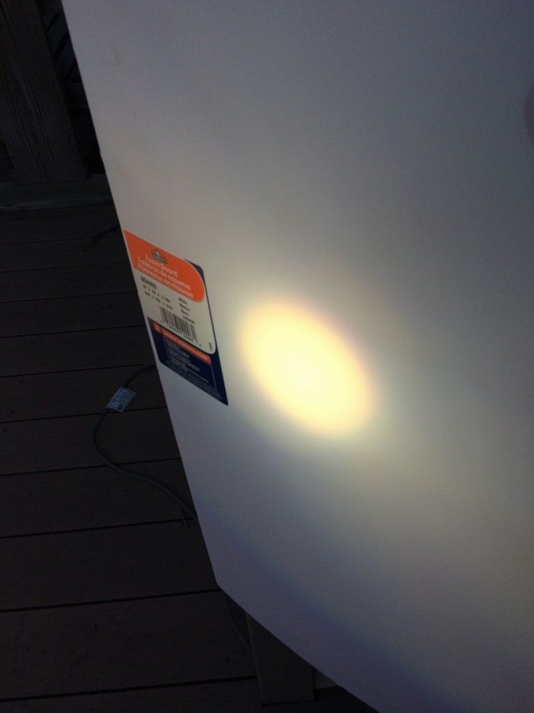
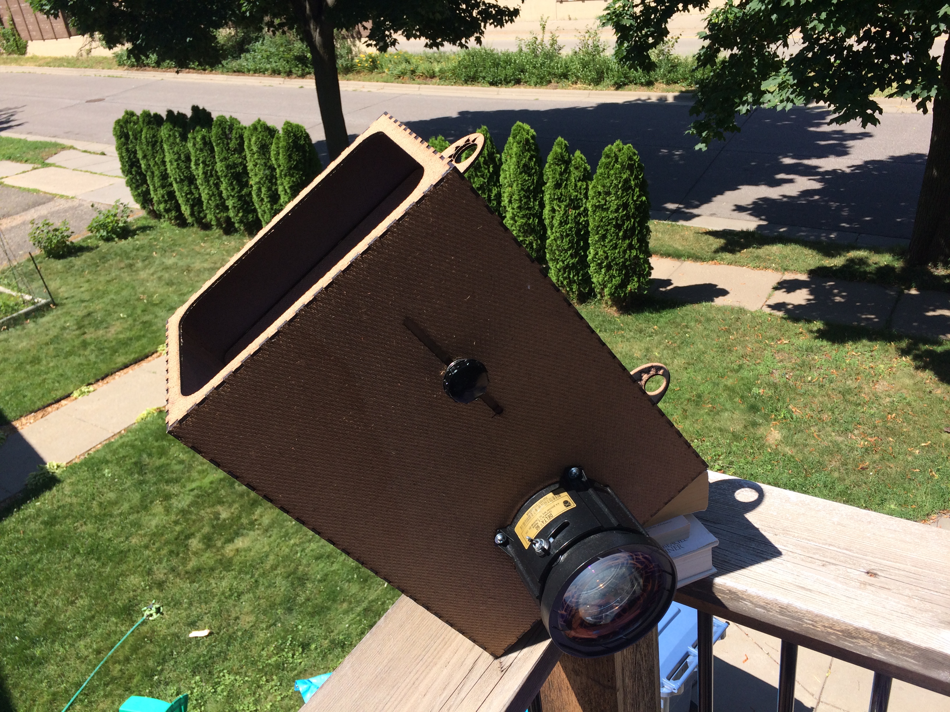
The solar projector on a railing, propped up by books, catching the sun.
Materials
Determining the Lens Focal Lengths
I bought Fresnel lenses sold as page magnifiers and glass lenses that were sold to match particular TV models. I had no real information about their focal lengths. So, I took two different steps to come up with approximate focal lengths. The first thing that I did was set up a small lamp in my bedroom at night. I then positioned the light and a white backdrop at the distance that I needed them to be so that when the image of the light was in focus, the lens was half way between the light and the backdrop.
Then, I used the equation:  to calculate the focal length. Here
  is the distance from the lens to the object and
  is the distance from the lens to the image. Since I made those both equal here, then the focal length is half the distance from the lens to the backdrop.
I determined that the focal length of my Fresnel lens was about 300mm and that the focal length of my glass lens was about 90mm.
Later, I verified these numbers by taking taking the lenses outside. I placed them to focus the sun on the sidewalk. Be very careful in this step. Concentrating the sun with a lens is a great way to start a fire. That’s why I did this on the sidewalk. I verified that when the lens was at the calculated focal length, the sidewalk started to smoke.
Preparing the Telescope
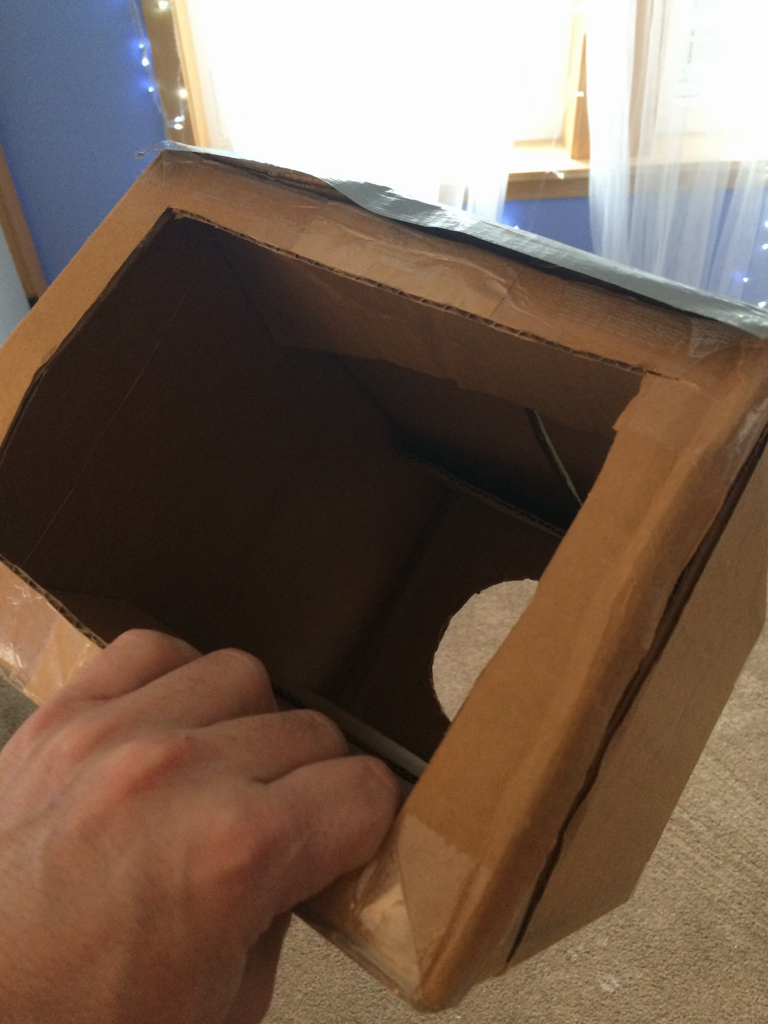
So, my brushing up on my lens equations and some common sense made me think that to project the sun, I wanted there to be about 390mm between my two lenses. I still wanted to verify this before really committing. So, I cut up a cardboard box so that I could put a Fresnel lens in one end and a glass lens in the other.

This worked out well enough and I had experimental verification of how far I wanted from the Fresnel lens and the glass lens.
So, then I started sketching out plans for the actual projector.
I decided that I wanted a 90-degree bend in the light path. With the bend, I can point the objective lens up toward the sun and have the projection screen set up any distance off to the side rather than having to set it up between the projector and the ground.
Once that was done, I put together plans to cut out a real box using a laser cutter.
In my first attempt, I had apparently gotten one of the pieces of my drawing misaligned. It was together enough though to do some initial experimentation. In the initial experimentation, it was really obvious that I needed to add a viewfinder.
The Viewfinder
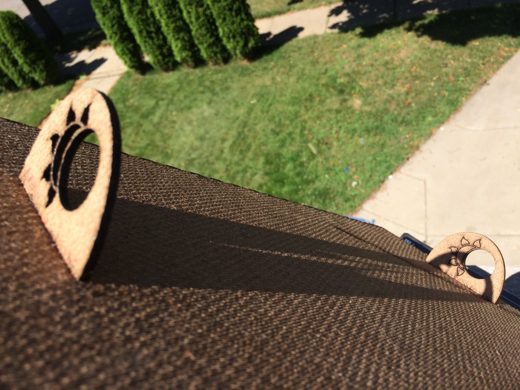
After manually attempting to point the camera at the moon and other dim objects, I decided that I needed a viewfinder of some sort. I decided that I needed a viewfinder where you could either look through it at a dim object or line things up based on shadows from the sun. I was about to just go with a cross-hairs type pattern when I thought, now would be a very nice time to pretty it up. I searched around a bit for sun icons and stumbled upon this gorgeous eclipse icon.

I made the front viewfinder with both the sun and the moon cut out. I made the rear viewfinder with the moon cut out and the sun just engraved. This is supposed to be a reminder that you shouldn’t be trying to line up the sun by looking through the viewfinder. You can use the viewfinder to line up the moon and you can use the shadow of the front viewfinder on the rear viewfinder to line up the sun.
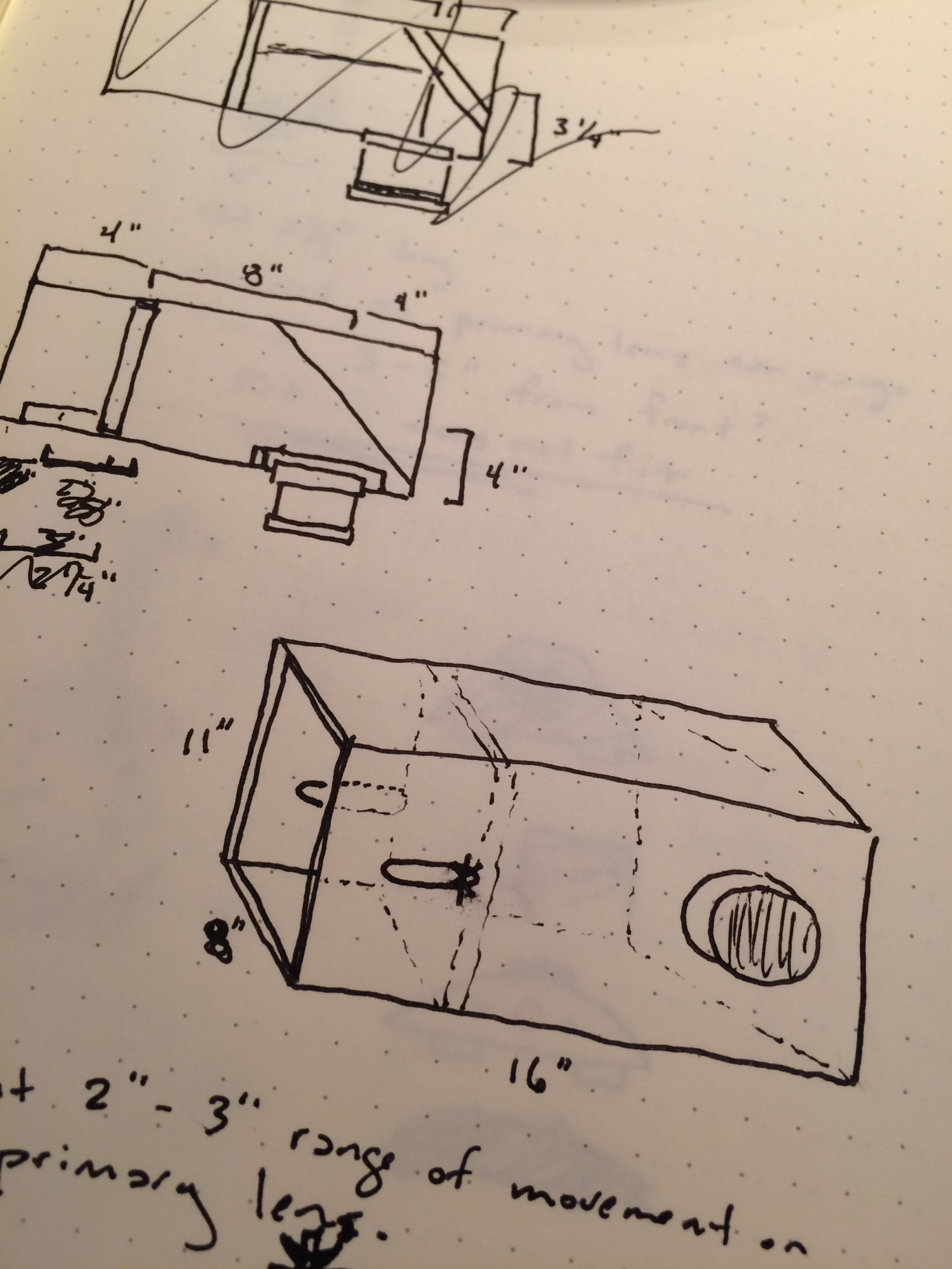
Final Plans
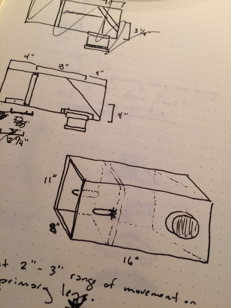
Here are the  sun-projector plans. The red lines are to be cut through. The blue lines are to be cut through if you want to build a straight-through projector. The green lines are to be cut through if you want to build the projector with a bend as I did. The yellow lines are only to be etched. Note: the entire dimensions depend on your lenses having a light path in the neighborhood of mine….. something between 300mm and 400mm. If you don’t have lenses in that range, you probably have to design your own.

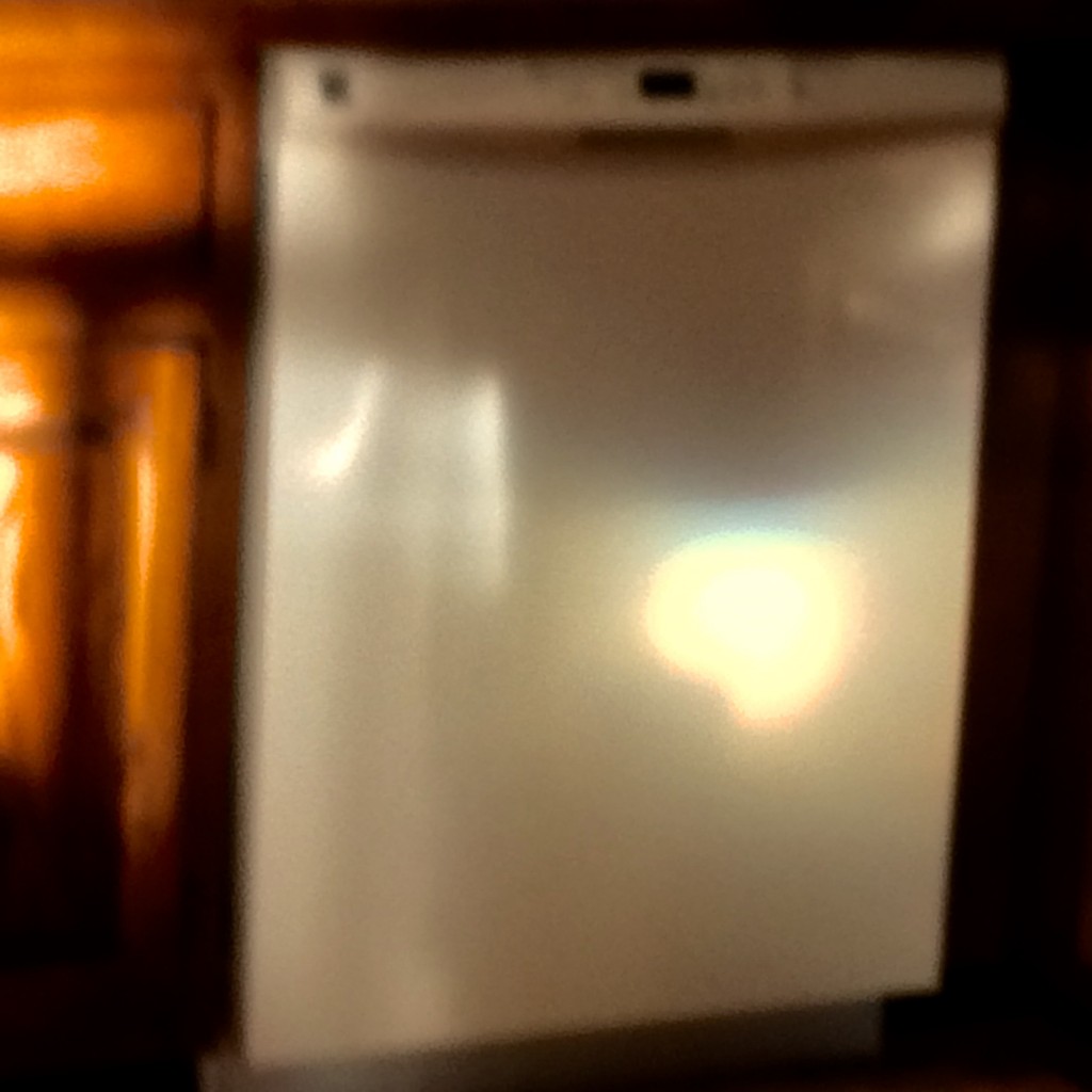
Here is an image of the sun. The projected image of the sun is 100mm in diameter. You can’t tell too much in the picture, but in real life you can see two shadow images of the sun because I am using a $5 rear-reflecting mirror instead of $85 front-reflecting mirror. Meh.
Next Steps
Next, I am planning to try to make a base in which to sit the projector to make it easier to point it at the desired spot in the sky.


